When choosing an electroencephalogram (EEG) device within the constraints of a project requirements, it is important to find the maximum performance possible by balancing features and value. This article focuses on the EEG sensor layer features, including the type of sensor (dry/wet), shielding, and electrode placement, in order to give guidelines to help in the selection process.
Overview of EEG technical features
Electroencephalography (EEG) device technical features can be divided into three main areas:
-
The sensor or headset area (sensor layer), addressed in this post.
-
The amplifier (acquisition layer), which can be subdivided into analog and digital subareas
-
The amplifier connectivity area (connectivity layer), with other features like dimensions, power, weight, etc.
In this post we will focus on the first area, the sensor layer.
EEG headset sensor layer
The EEG sensor layer comprises the sensor-body interface and the signal transmission to the amplifier.
1. Number of EEG electrodes / channels
We measure the EEG activity as the difference in voltage between two electrodes. As a general rule, one fixed electrode is chosen as the reference for all the other electrodes. Therefore, an EEG headset contains three types of electrodes:
-
Recording electrodes: placed over the specific scalp locations that we want to measure.
-
The reference electrode: one whose signal is subtracted from each of the recording electrodes.
-
The ground electrode: used to place both the amplifier and the body to the same potential and to reduce common-mode interference.
When talking about the number of electrodes, it always refers to the EEG recording electrodes only, since the reference and the ground are always needed. For example, a 32-channel EEG device has 32 recording channels, plus ground and reference.
The number of EEG channels determines the amount of information that we will be able to process. Although it is difficult to generalize, a general division could be:
-
>64ch: High-density neuroimage research or EEG studies that rely heavily on source localization and signal processing filtering, or very localized brain processes.
-
32-64ch: Neuroimage research studies that rely on source localization or EEG imaging (with heavy EEG artifact filtering).
-
19ch: the standard 10-20 system used in clinical research and practice.
-
16-32ch: Applied neuroscience research areas, like brain-computer interfaces, biomedical engineering, neural engineering, psychophysiology, etc.
-
8-16ch: Neurotechnology for motor neurorehabilitation, cognitive neurorehabilitation, consumer neuroscience, etc. (where we usually know the activity and area of the brain we need to measure).
-
<8ch: For very specific applications that involve the measurement of a well-defined neural process and require a simple and quick set up (e.g., traditional neurofeedback over one cortical location, measurements of sleep EEG, etc.).
2. EEG electrode placement (fixed vs interchangeable)
EEG sensor positions usually follow the International 10-20 System that labels them according to location of the scalp electrodes and the underlying area of the brain. The labels have a letter to identify the area of the brain that is being recorded by each electrode.
The principal brain areas are pre-frontal (Fp), frontal (F), central (C), temporal (T), parietal (P), and occipital (O). Regarding their lateralized location, odd numbers (1,3,5,7) refer to electrodes placed on the left hemisphere, even numbers (2,4,6,8) refer to those on the right hemisphere, whereas electrodes over the midline (zero line) are labeled with the letter “z”.
Depending on the percentage of the distance between sensors, we have the 10-5, the 10-10 and the 10- 20 system. It is highly advisable to follow this 10-20 EEG electrode placement standard as otherwise the data collection and data analysis (and thus the results) are not comparable with others in the research literature.
Commercial EEG-based headsets feature either fixed or interchangeable sensor positions. The sensors of systems with fixed positions cannot be moved from one location to another, while the systems with interchangeable positions can be moved to accommodate different experimental setups.
If you are interested in learning more about this topic, check out this article: EEG Electrode Placement: Fixed vs. Variable
As a general rule when selecting an EEG headset, a system with interchangeable sensor locations is preferred for exploratory research phases, where it is important to have a high head sensor coverage and the flexibility to explore. Systems with fixed sensor locations are for neurotechnology applications where the location of an electrode is always the same and the priorities are usability and comfort. Check this article for a deeper discussion about how to select a dry-EEG system.
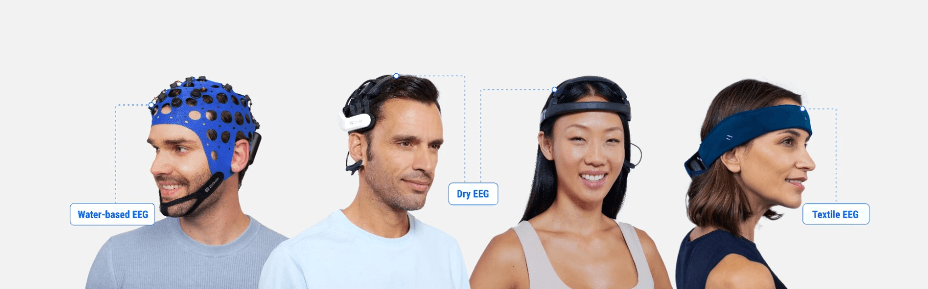
3. Type of EEG sensors
Dry EEG, semi-dry EEG, saline EEG, gel EEG electrodes: The difference between these electrodes is the electrolytic substance applied between the electrode and the scalp, used to improve conductivity.
-
Dry-EEG electrodes do not require the use of any electrolytic substance, making the contact directly with the scalp. The main advantage is that they are fast to place, do not require any additional instruments like syringes, do not require cleanup of the head, and do not require heavy hygienic procedures on the equipment afterward.
The main disadvantage is the high contact impedance between the sensor and the skin, which requires the amplifier to deal with more noise and artifacts.
Therefore, to achieve the same signal quality than those systems that use electrolytic substances, the amplifier must have better performance: First, it must have higher input impedance to avoid signal attenuation. Second, it must provide active shielding techniques to minimize coupled artifacts, such as power line interface or movement artifacts as examples. (See Li et al., 2018.) -
Wet EEGs: Semi-dry, saline or gel-based EEGs require the application of an electrolytic substance between the scalp and the electrode to obtain good contact and reduce the impedance of the skin-electrode interface. It allows the system to improve features and performance by reducing noise and artifact sensivity.
Beyond the typical electrolytic gel systems, there are also semi-dry electrodes that use only tap water (also denoted water-based), and others that use saline solutions to increase water conductivity properties.
In this table, we summarize some properties adapted from Searle et. al., 2000; Grozea et. al., 2011.
There are two important aspects to consider here:
-
EEG amplifiers correctly designed for dry or semi-dry EEG sensors can work perfectly with saline water or gel-based EEG sensors due to their higher performance specifications. However, the opposite is not true, and we may expect lower signal to noise ratio with high levels of noise and artifacts if we use dry or semi-dry sensors with an amplifier that is not optimized for them.
-
The selection of the sensor determines the potential application, due to the ergonomics and usability that they provide. Yet, this selection cannot be done without taking into account the input biosignal amplifier features, like shielding or input amplifier impedance, among others.
The general selection rule is: the higher the conductance in the electrode-skin interface (which depends on the skin preparation and the applied substance), the lower the signal transportation and amplifier features required, but always at the cost of lower ergonomics and usability.
4. EEG sensor shielding
Active vs. Passive electrodes: The main difference between these two technologies is that active electrodes have an electronic circuit embedded between the sensory part and the wire, while in passive electrodes these two sections are welded directly together (Figure 4a and 4b).
The following table summarizes the advantages and disadvantages of active and passive electrode systems (see Table 2).
5. EEG electrode cable shielding
Active vs. passive vs. no cable shielding: This applies to the cable design and the type of signals injected on the shield to protect the EEG signal from electromagnetic interference and noise.
Electromagnetic interference is common in EEG monitoring and recordings, introducing electrical noise that impacts the recorded signals. These interferences are caused by stray capacitance (i.e., unavoidable and unwanted capacitance that exists between the parts of an electronic component or circuit because of their proximity to each other). This “connects” the device and the user to surrounding interference sources, like computers (logic circuits), switching power supplies, AC power lines, radio transmitters, etc. (Rich, 1982).
- No shielding: The simplest cable has no shielding at all (Figure 5). This kind of cable has just one wire to transmit the EEG signal, which is exposed to the environment noise. In this case, the EEG signal is highly susceptible to any kind of coupled artifact like the movements of the participant, and all the electromagnetic interferences.
- Shielding: The more recommended way to reduce these artifacts is to shield the cable. Shielding involves covering the inner wire with a braided one around it, creating a coaxial cable (Figure 6). The shield acts as a Faraday cage to reduce any electrical noise that affects the signal. With this technique, the EEG signal travels protected along the inner wire, while the outer braid covers and protects it from the external coupled artifacts.
This braid could be connected in two different ways, making an active or passive shielding (Figure 7):
-
With the passive shielding, the shield is connected to a fixed potential (generally the ground).
-
With the active shielding, the inner wire signal is fed back to the braid (i.e., there is the same potential in the inner and outer wire).
In EEG recordings, where we have a signal generator (the brain) with low amplitude and high output impedance, it is important to completely decouple the inner wire from the outer environment. The best way to do it is by using active shielding, which “eliminates” the stray capacitances between the inner wire and outer braid, isolating the registered signal perfectly from the outer mesh and thus, from the surrounding environment. This is the reason why the performance of shielding techniques for EEG is (from low to high quality): No shield → Passive shield → Active shield. (Rich, 1983).
The general selection rule is that better shielding allows higher quality signal transmission to the amplifier. Active shielding is becoming the gold standard in EEG amplifiers as it is not an expensive feature, yet it has a very high impact on signal quality.
Real-world examples
Here are two examples of real-world EEG montages and artifact tests (arm and eye movements, eye open/closed, walking, etc) of two commercial systems with their respective features. The main value with respect to other EEG technologies is the practicality for the researcher and comfortability for the user, without losing signal quality.
-
Diadem EEG: a mobile device designed to be the very first reliable EEG (very high signal quality) with self-placement function to afford neuroscience applications (in and out-of-the-lab) that need to measure only frontal and posterior brain areas.
-
Versatile EEG: designed to be the most practical EEG system for research applications, with very good signal quality in the presence of environmental or participant artifacts. These all-purpose semi-dry EEG caps with 8, 16, 32, and 64 channels are mobile EEG devices for real-time recording of the electrical activity of the brain, and with a sampling rate of 256Hz at 24 bits.
About the author
Aitor Ortiz.
Aitor Ortiz obtained his degree in telecommunication engineering (2012) and a MSc in biomedical engineering (2013) by the University of Zaragoza (Spain). From 2012 to the present he works as a research scientist and the chief of the electronics department for Bitbrain. His main research interests are on the development of bio-potential recording devices, mainly focused on electroencephalograms for brain-computer interfaces.
Bibliography
- Grozea, C., Voinescu, C. D., & Fazli, S. (2011). Bristle-sensors—low-cost flexible passive dry EEG electrodes for neurofeedback and BCI applications. Journal of Neural Engineering, 8(2), 025008. doi: 10.1088/1741-2560/8/2/025008
- Li, G., Wang, S., & Duan, Y. Y. (2018). Towards conductive-gel-free electrodes: Understanding the wet electrode, semi-dry electrode and dry electrode-skin interface impedance using electrochemical impedance spectroscopy fitting. Sensors and Actuators B: Chemical, 277, 250–260. doi: 10.1016/j.snb.2018.08.155
- Rich, A. (1982). Understanding Interference-Type Noise. Analog Dialogue, 16(3), 16–19.
- Rich, A. (1983). “Shielding and guarding” Analog Devices Application Note No.AN-347.
- Searle, A., & Kirkup, L. (2000). A direct comparison of wet, dry and insulating bioelectric recording electrodes. Physiological Measurement, 21(2), 271–283. doi: 10.1088/0967-3334/21/2/307.
You might also be interested in:
- What is QEEG brain mapping and normative databases?
- EEG-based Neurotechnology for Human Enhancement and Rehabilitation
- EEG Synchronization With Other Biosensors and Software
- Epilepsy and EEG seizure-detection
- The Forgotten History of Alpha Brain Waves
- Advances in motor neuroprosthetics improve mobility in tetraplegics
- What is neurorehabilitation and 4 leading projects in Europe
- The Use of EEG for ADHD Diagnosis and Treatment
- The Procedure and Uses of the EEG Test