When selecting an electroencephalogram (EEG) device for your project, finding the perfect balance between features and value is key to achieving optimal performance. In this article, we delve deeper into the essential amplifier features, building upon our previous discussion on the main features of EEG sensors. We'll explore critical aspects such as sampling rate, bandwidth, noise level, CMRR, and more, providing valuable insights to help you make informed decisions for your EEG endeavors.
Overview of EEG technical features
Electroencephalography (EEG) measures the electrical activity of the human brain. Its technical aspects can be divided into three main areas:
-
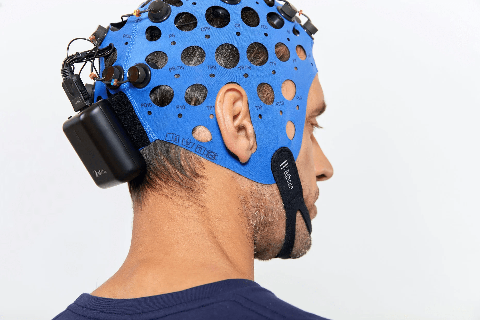
The EEG headset (sensor layer).
-
The EEG amplifier (acquisition layer), which encompasses both analog and digital components discussed in this post.
-
The amplifier connectivity layer, along with other important features such as dimensions, power consumption, and weight.
The EEG amplifier plays a pivotal role in the data acquisition process. Its primary function is to capture, amplify, and convert the analog electrical signals from the sensors into a digital format that can be processed by the computer.
We describe next a summary of the features and common values of modern EEG amplifiers:
- Sampling rate (frequency): > 256Hz.
- Bandwith: 0Hz to >80Hz.
- Resolution: >= 24 bits.
- Input range: > 50mV.
- Input refrred noise: < 1 microVrms.
- Common Mode Rejection Ratio (CMRR): > 80dB at 50/60Hz.
- Input impedance: > 100 MOhm.
- Impedance Monitor: off line is a must and online is highly desirable.
Sampling rate
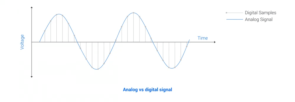
The EEG frequency or sampling rate describes the number of times that the signal is measured per unit of time, usually given in Hertz (Hz) = 1/second (Figure 1). Notice that although the EEG is an analog signal (continuous time series), it has to be converted into a digital signal (discrete in time) in order to be processed by the computer.
EEG signals carry valuable information within a bandwidth ranging from 0.5 Hz to 80 Hz, known as EEG frequency bands in the power spectrum: delta (0.5 – 4 Hz), theta (4 – 8 Hz), alpha (8 – 12 Hz), beta (16 – 24 Hz), and gamma (up to 80 Hz), see Weiergräber et al., 2016. It's worth noting that there are also brain potentials and applications utilizing lower frequency ranges (DC – 0.5 Hz), referred to as slow cortical potentials (Garipelli et. al., 2013).
For accurate measurement, the sampling rate must be at least twice the maximum frequency of the signal, as per the Nyquist sampling theorem, see (Jones, 2014). While a sampling rate of 160 Hz captures the 0 (DC) to 80 Hz range with two samples per signal period, standard amplifiers typically acquire data at frequencies of at least 256 Hz. Higher sampling rates offer enhanced resolution within the EEG bandwidth (0 to 80 Hz), but do not provide additional information.
In neuroimaging research, a minimum sample rate of 256 Hz is generally acceptable. For more demanding scenarios, 512 Hz is common, with some applications requiring rates of up to 1024 Hz, considered very high for EEG data. Real-time neuroscience and mobile EEG applications typically use a standard sampling rate of 256 Hz for near real-time data transfer and processing.
Bandwidth
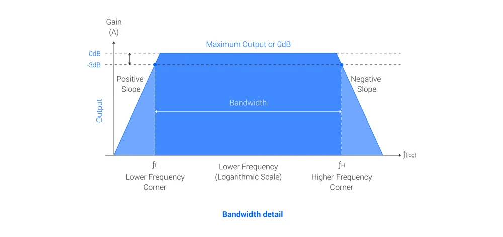
The bandwidth represents the effective frequency range that an EEG system can measure, determined by the sample rate (as discussed earlier) and the internal filters of the amplifier.
Amplifiers are often equipped with internal filters. A low pass filter to comply with the Nyquist theorem and a high pass filter to remove EEG offsets and DC components, preventing electronics saturation (amplifiers lacking high pass filters are called DC coupled). These filters are designed to attenuate low and high frequencies. The bandwidth refers to the frequency range where the signal's amplitude is attenuated by less than 3dB.
The sampling rate indicates how frequently the signal is measured within a given time frame, usually expressed in Hertz (Hz). One Hz is one measurement per second. It's worth noting that while EEG is an analog signal (continuous in time), it needs to be converted into a digital signal (discrete in time) for efficient processing by the computer.
The choice of bandwidth depends on the intended usage. In general research settings, it's common to capture all frequencies up to 80Hz. However, it's important to note that many EEG monitoring applications rarely utilize frequencies above 30-40Hz. As a result, certain amplifiers tailored for specific applications, such as dry-EEG for home use, may set the cutoff frequency to 30-40Hz to minimize noise without sacrificing signal quality at lower frequencies.
For recording low EEG frequencies, the amplifier should either be DC coupled or have a high-pass cutoff frequency close to 0Hz. It's worth mentioning that DC coupled amplifiers can capture various slow cortical potentials, which is an important factor to consider.
Resolution
As mentioned earlier, the analog EEG signal voltage undergoes a digitization process, where it is converted into a digital value. This conversion is carried out by an Analog to Digital Converter (ADC), which codes each voltage value using a specific number of bits. This number of bits determines the resolution of the amplifier.
It's important to note that in some contexts, the term 'resolution' can also refer to the smallest part of a signal that can be distinguished. This is determined by the ratio between the input signal range of the amplifier (as discussed below) and the number of quantization levels (2 raised to the power of the number of bits).
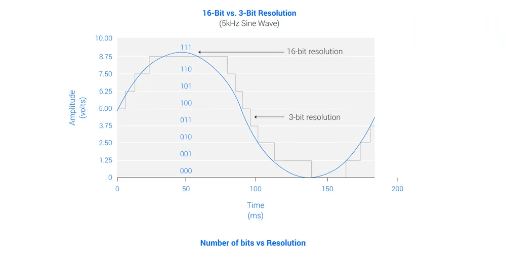
When choosing an EEG system, it's important to consider that standard resolution in clinical or high-quality research EEG amplifiers typically starts at 24 bits.
Input range:
The input range of an amplifier refers to the maximum amplitude signal it can record before reaching saturation. It's important to note that the output range of an amplifier is fixed (usually denoted as Vcc) and depends on its power supply. Therefore, the input range is determined by both the output range and the amplifier's internal gain, which indicates how much the input signal is amplified: Vout = G x Vin. For instance, if the amplifier can record between 1V and its gain is 2, the input range will be 500mV.
EEG amplifiers must have an input range that encompasses not only the minimum and maximum values of EEG signals (which can range in the tens of volts) but also values from other physiological or mechanical processes that may interfere with EEG, such as EOG (which can be in the hundreds of volts), EMG (typically in the tens of millivolts), and offset voltages (also in the tens of millivolts (Harrison, 2007). If the physical signal exceeds the input range, it gets clipped and isn't measured (refer to Figure 4).
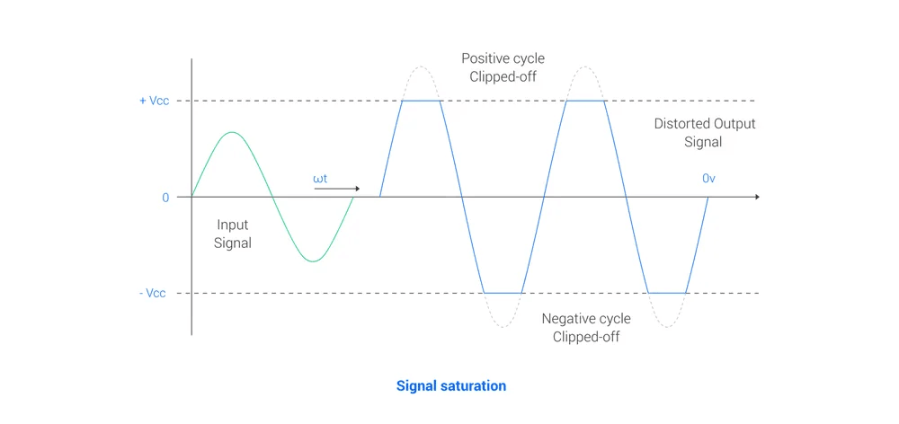
In DC-coupled mode, the input range should be at least 50mV. With this range, the amplifier can effectively record all the signals mentioned earlier without risk of saturation.
Input referred noise
Input-referred noise refers to the voltage or current noise produced by the amplifier's internal circuitry (even when there's no signal present at the input). Given that EEG signals can have amplitudes as low as a few microvolts, it's crucial for this noise to be less than 1μVrms.
Common Mode Rejection Ratio (CMRR)
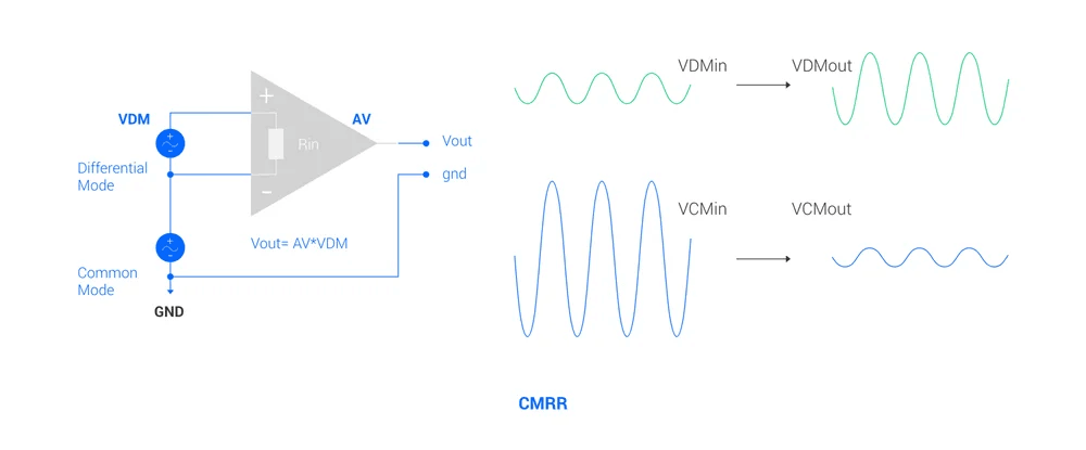
The Common-Mode Rejection Ratio (CMRR) measures a differential amplifier's ability to suppress or reduce the common-mode voltage (VCM), which is a voltage that remains constant on both the positive and negative inputs of the amplifier. At the same time, it amplifies the differential mode voltage (VDM), which is the voltage difference between the positive and negative inputs (refer to Figure 5).
In the context of an EEG amplifier, CMRR indicates how well the device can amplify the EEG signal (the voltage difference between electrode "n" and the reference electrode) while reducing artifacts, such as 50/60Hz noise present in both the electrode "n" and the reference electrode.
A higher CMRR indicates better amplifier performance, as it means the device can attenuate unwanted common-mode signals more effectively. According to Mettingvanrijn et al., 1994, a biosignal amplifier should have a CMRR of at least 80dB at 50/60Hz.
For the selection of the EEG amplifier, the common-mode rejection ratio must be at least 80dB at 50/60Hz. The higher CMRR, the better the performance, being 100 - 110 dB a common value among commercial amplifiers.
Input impedance
The input impedance refers to the impedance of the first stage of the amplifier. In this context, we distinguish between electrode impedance, which is the impedance between the electrode and the skin; and input impedance, which is the constant impedance defined by the input circuit of the amplifier.
EEG amplifiers receive signals from electrodes with relatively high impedance, ranging from several kilohms in wet electrodes, to several hundreds of kilohms in dry electrodes. Therefore, it's crucial to minimize any attenuation of these already very weak signal amplitudes (measured in microvolts) to prevent loss of resolution. Drops in amplitude, which can vary across electrodes depending on their impedance, can reduce the Common-Mode Rejection Ratio (CMRR) and increase noise (Kappenman et al., 2010). The only way to maintain signal amplitude without reducing electrode impedance is to use an amplifier with high input impedance (Ohm’s Law).
When choosing an EEG system, it's essential to consider that the higher the input impedance of the amplifier, the better it will respond to high electrode impedance. This is specially important when using dry EEG electrodes. EEG recordings typically have electrode impedances ranging from 1 kilohm to 1 megohm (Rosell et. al., 1988). Therefore, an amplifier should ideally have a common input impedance of at least 100 megohms (100 times the electrode impedance), ensuring that signal attenuation remains below 1% (Mettingvanrijn et. al., 1991).
Impedance monitor
It's crucial to monitor the signal quality of each channel during EEG setup and, if possible, during EEG recording. One of the key parameters affecting this quality is the sensor impedance or skin-electrode impedance. That's why typical EEG amplifiers include an impedance monitoring feature, either during setup alone or throughout both setup and recording.
- During EEG set up: Monitoring impedance helps ensure a good EEG setup. However, it assumes that once the cap is correctly placed, impedances won't change during recording.
-
During the EEG setup and recording: Monitoring impedance over time allows for adjustments during recording and can be factored into EEG signal processing.
The impedance monitor works by injecting an artificial signal that is measured by the EEG electrodes. If the signal is within the EEG bandwidth and used during the EEG recording, the EEG data can be contaminated. This can become problematic when the impedance monitoring signal is used in low frequencies, as they will become impossible to analyze later on. For this reason, impedance monitoring during the recording must be at higher frequencies than the EEG band.
When selecting an EEG system, the impedance monitoring during setup is highly desirable. High-performance EEG systems also offer impedance monitoring during recording, but it's crucial that this operates at frequencies above the EEG band (typically above 60Hz in standard setups and above 80Hz when exploring the gamma band).
Bitbrain solutions
Bitbrain specializes in developing innovative devices with excellent usability for multimodal monitoring, encompassing semi-dry EEG, dry-EEG, and textile-EEG systems, as well as biosignals (ExG, GSR, RESP, TEMP, IMUs, etc.), and eye-tracking solutions (screen-based and mobile platforms).
The software tools facilitate the design of experiments, effortless data gathering with over 35 synchronized sensor types, and extensive data analysis covering a broad spectrum of emotional and cognitive biometrics.
Bitbrain's platforms offer interconnectivity with other systems through LSL, ePrime, Matlab, or Python, providing flexibility and compatibility for diverse research and application needs. Our systems are used by scientists in high-impact and peer-reviewed publications in a wide range of research applications, including neuroscience, psychology, education, human factors, market research and neuromarketing, and brain-computer interfacing.
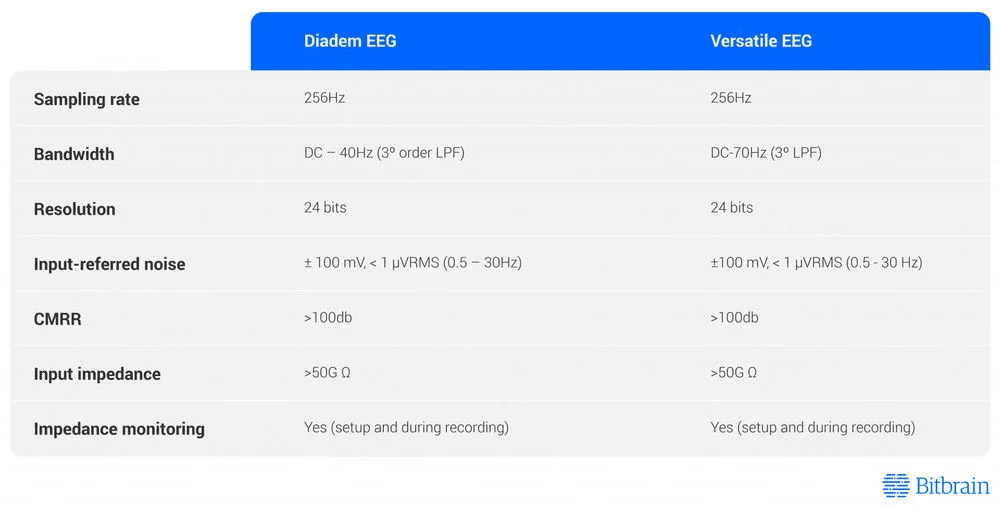
Below some examples of Bitbrian system and the EEG features of their amplifiers:
- Diadem EEG: designed to be the very first reliable dry EEG headset (very high signal quality) with self-placement function to support neuroscience applications or products that need to sense only frontal and posterior brain areas.
- Versatile EEG: designed to be the most practical EEG system for research, with very good signal quality in the presence of environmental or participant artifacts.
Bibliography
- Garipelli, G., Chavarriaga, R., & Millán, J. D. R. (2013). Single-trial analysis of slow cortical potentials: a study on anticipation related potentials. Journal of Neural Engineering, 10(3), 036014.
- Harrison, R. R. (2007). A Versatile Integrated Circuit for the Acquisition of Biopotentials. 2007 IEEE Custom Integrated Circuits Conference.
- Jones, M. (2014). Test Equipment Principles. Building Valve Amplifiers, 235–380.
- Kappenman, E. S., & Luck, S. J. (2010). The effects of electrode impedance on data quality and statistical significance in ERP recordings. Psychophysiology.
- Mettingvanrijn, A. C., Peper, A., & Grimbergen, C. A. (1991). High-quality recording of bioelectric events. Medical & Biological Engineering & Computing, 29(4), 433–440.
- Mettingvanrijn, A. C., Peper, A., & Grimbergen, C. A. (1994). Amplifiers for bioelectric events: A design with a minimal number of parts. Medical & Biological Engineering & Computing, 32(3), 305–310.
- Rosell, J., Colominas, J., Riu, P., Pallas-Areny, R., & Webster, J. (1988). Skin impedance from 1 Hz to 1 MHz. IEEE Transactions on Biomedical Engineering, 35(8), 649–651.
- Weiergräber, M., Papazoglou, A., Broich, K., & Müller, R. (2016). Sampling rate, signal bandwidth and related pitfalls in EEG analysis. Journal of Neuroscience Methods, 268, 53–55.
Related Resources:
- What is EEG and what is it used for? : A beginner-friendly introduction to EEG: how it works, its main applications in medicine and research, and the types of devices available.
- Main Features of the EEG Sensor Layer Explained: Learn about the sensor layer in EEG devices: types, materials, and their impact on signal quality.
- EEG Synchronization With Other Biosensors (EEG, ECG, EMG, eye tracking, etc.), and Software: Understand what neural synchronization in EEG is and why it matters for studying brain connectivity.
- The Wet EEG Cap: Water, Saline, and Gel Differences: Everything you need to know about traditional wet EEG caps, from preparation and conductive gel application to maintenance and when they are the optimal choice for your study.
- What is BCI? An introduction to brain-computer interface using EEG signals: An introduction to the mechanisms of Brain-Computer Interfaces (BCI), detailing how they translate neural activity into computational commands.
- Modern BCI-based Neurofeedback or EEG Biofeedback for Cognitive Enhancement: How BCI-based neurofeedback uses real-time EEG to train brain activity and improve memory, attention, and cognitive performance in both clinical and healthy populations.
- Sleep EEG for Diagnosis and Research: How EEG is used to study sleep stages, diagnose sleep disorders, and explore their impact on cognition and mental health.
- How EEG is Changing Driver Fatigue Detection in Real Time: How EEG and AI are enabling real-time fatigue detection in drivers, pilots, and other high-risk professionals.
- Epilepsy and EEG seizure-detection: How EEG is used to detect and classify epileptic seizures, support diagnosis, and guide treatment in patients with epilepsy.